Notch, bend and straighten in Autodesk Inventor

Peter Crawley
Former Design and Manufacturing Technical Specialist at CadproI was asked recently if there was a method to notch, bend, and straighten hollow sections using Inventor. I’ve discovered a couple of methods, both of which are shown below. There are probably more, but these two look worthy of sharing.
Being a fan of Frame Generator, I was keen to see if I could find a method that could be used to unfold an existing frame. In conjunction with an unlikely partner (Sheet Metal) it can! See the second method below for details. (Notch and bend description – see here)

Method 1 – Notch and bend using the “Bend Part” feature
This method assumes you can straighten the design in your head before modelling it and bending it into shape. If you have the brain for that process, then this is the method for you because it’s quick and easy. If you’d prefer to model the final result and then “unfold” it, skip over to Method 2 below.
Depending on your preference for modelling steelwork, this might appeal because it uses standard sketch-based features on the part file itself. I like it for its simplicity, but for multiple bends, it can quickly become difficult to calculate exactly where the cuts should be made, especially if the part is bent in more than one plane.

1. Create the sketch to cut out the material to make the notch. (I left a 1mm saw-gap at the point of the cut rather than making the cut-shape a simple triangle.)
2. Create the bend sketch-line on the inside wall of the RHS

3. Add the “Bend Part” feature keeping the radius small (1mm in this case) and the angle matches the cut-angle from the original sketch.

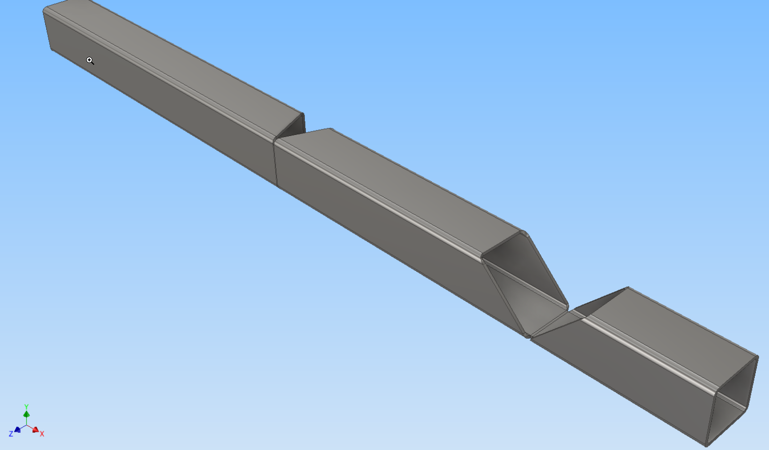
4. The result is a good clean bent part.
To straighten, simply move the “End of Part” marker above the “Bend” feature in the model browser.
Method 2 – Notch, bend, and straighten using Frame Generator
This method might take longer than the previous one, but you build the “bent” frame first. This means you get all the pieces in exactly the right places. The remaining steps simply join the separate sections using familiar sheet metal tools like corner seam and bend. To me, the method is most logical and least prone to errors because you model the result, then straighten it. The notch cutting happens as a result of the way frame members are joined together.
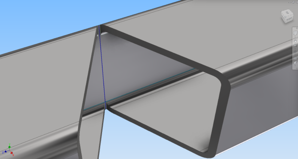
Note however that ends of steel where the notches are cut will look a bit odd. It’ll make sense when you model it because the part is really just sheet metal. (So you can even split it down the length and fold it completely flat for profile cutting.)

Modelling Process
1. Build the frame using traditional Frame Generator tools. Don’t waste any time on the end treatments! The frame members are going to be sacrificed later to make the notched and bent part.

2. Shorten all the parts just enough so there’s no overlap between them. Remember that you can shorten both ends at the same time using the second option in the Shorten/Lengthen dialogue box and that a negative value is used for shortening. When lengthening/shortening one end only, make sure you pick near the end you want to lengthen/shorten.

3. Save the assembly.
4. Create a new part and Derive in the Frame assembly. This will give you the base geometry for the unfolded part. In the derive dialogue box, output doesn’t really matter, as long as it’s a “solid” option (as opposed to surface or composite).

5. Convert the part to Sheet Metal and edit the Sheet Metal Style so the thickness matches the thickness of your steel parts (or they won’t unfold!). I would also recommend setting the bend radius to a small value, say 0.1mm.
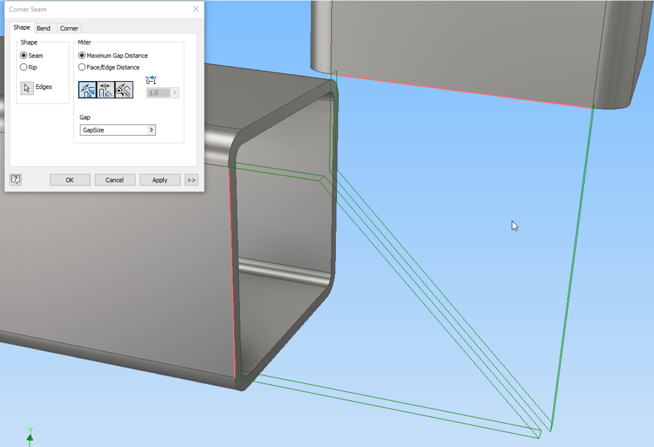
6. Use the Corner Seam tool to create the junction between all the edges of the members. (Yes, I was quite surprised when I found that this worked!) It might look odd when you do the first couple of edges, but it comes together nicely when you do the last edge.

7. Add the sheet metal “Bend” feature to the edge that will be unfolded. Think carefully about the edge that will be bent – I got it wrong once and ended up with self-intersecting model errors.
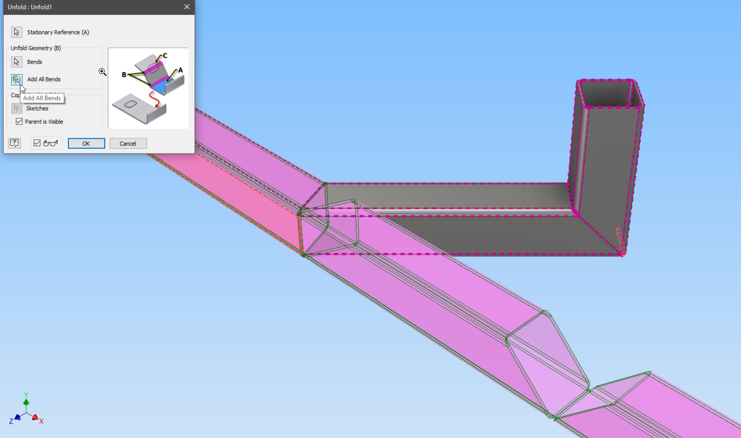
8. Add the Unfold feature, selecting a stationary face and the “all bends” option. Here you can clearly see the 45 degree notch.
The part is now ready for detailing.
9. The resulting unfolded part is quite satisfying – in a geeky way.
Final output
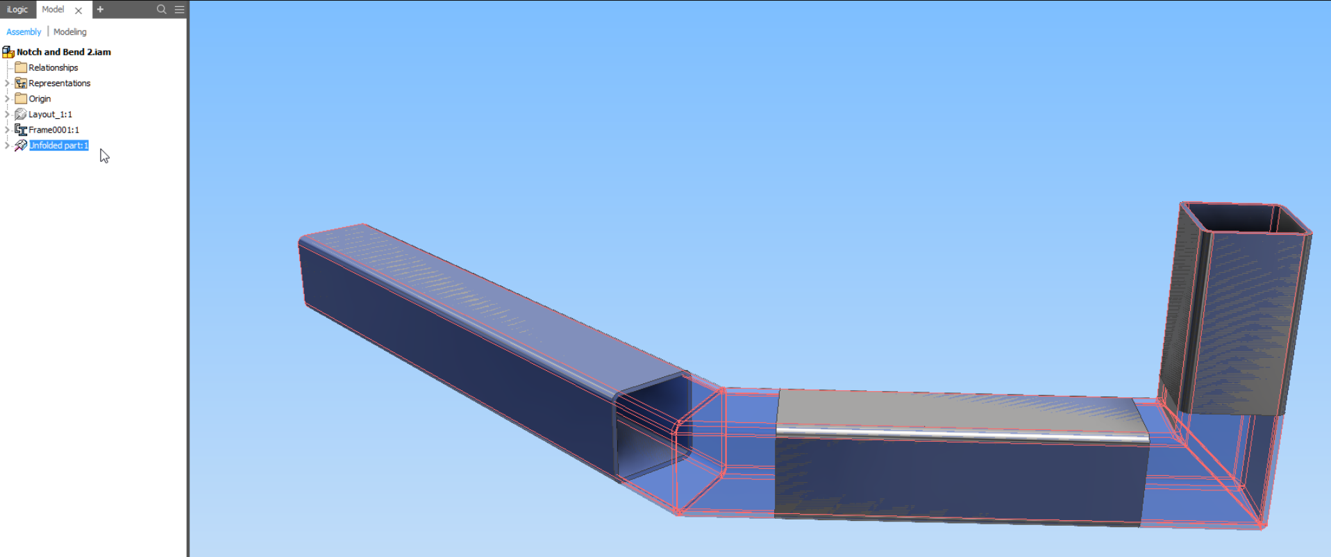
I inserted the folded part back into the original Frame Generator model. In the image below, the translucent blue part is the notched and bent part. Since it was derived from the original frame, placing it into the assembly using “Insert Grounded at Origin” will put it in precisely the right spot – no constraints needed.
What I really like about this method is that changes to the frame model will automatically update the bent part. You can now tweak the design without fear of remodelling.